Overview
Purpose of this document is to explain the tuning tables available in v1.0 of the bootmod3 CustomROM for the vehicles:
S55
N55-PWG
N55-EWG
N55-M2
Gen1 B48 and B58
Gen2 B48 and B58 (including Toyota Supra)
S58
For a high-level overview of the features in the bootmod3 CustomROM release as well as changes in the new Map Editor features refer to this document:
bootmod3 CustomROM Features + New Map Editor + UI Enhancements
CustomROM software on bootmod3 makes 4500-5000 calibration tables available for editing at this time. Up until the CustomROM release tuners have been calibrating using the pre-existing OEM calibration tables in the bootmod3 Map Editor. Both OTS and Custom maps were made in a way that suited a particular type of octane. Once flashed on the DME they’d be preset for the octane levels which they were tuned for, e.g. “My Custom 93 octane map”, “My Other Custom E50 octane map”, “Super aggressive E85 map”, and so on.
Map Switching allows for setting up 4 individualized calibrations inside a single flashable map. In addition, separate Anti-Lag tables are available that change ignition timing, fuel and torque/boost targets while Anti-Lag is active. Flex Fuel carries its own separate set of very similar tables and blending between Map Slot tables (lets refer to them as base maps) and the Flex Fuel tables can then be enabled on top of any given Map Slot as needed.
Map Switching - Example Map Setup
When in the car and flashed on the CustomROM map, Map Slots can be switched using the steering wheel Cruise Control RESUME and UP/DOWN buttons as explained in the document linked above.
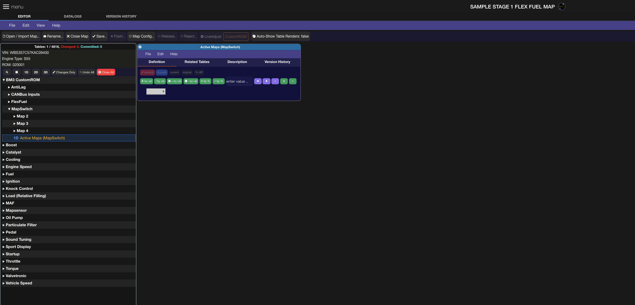
When starting out with a custom Tune Request the base map is sent to the Tuner based on the CustomROM matching the vehicle’s calibration details and only a single Map Slot (map slot 1) enabled by default and all tables in map slots 2-4 pre-set to their corresponding stock calibration values as the base to start tuning with.
In the case Map Switch-ability isn’t a concern for the custom map being built, then the value in the example below can remain at 1, for one map slot.
In the above example, we’ve activated all four switchable maps meaning tables under BM3 CustomROM → MapSwitch → Map 2, 3 and 4 will be tuned for a multi-map setup.
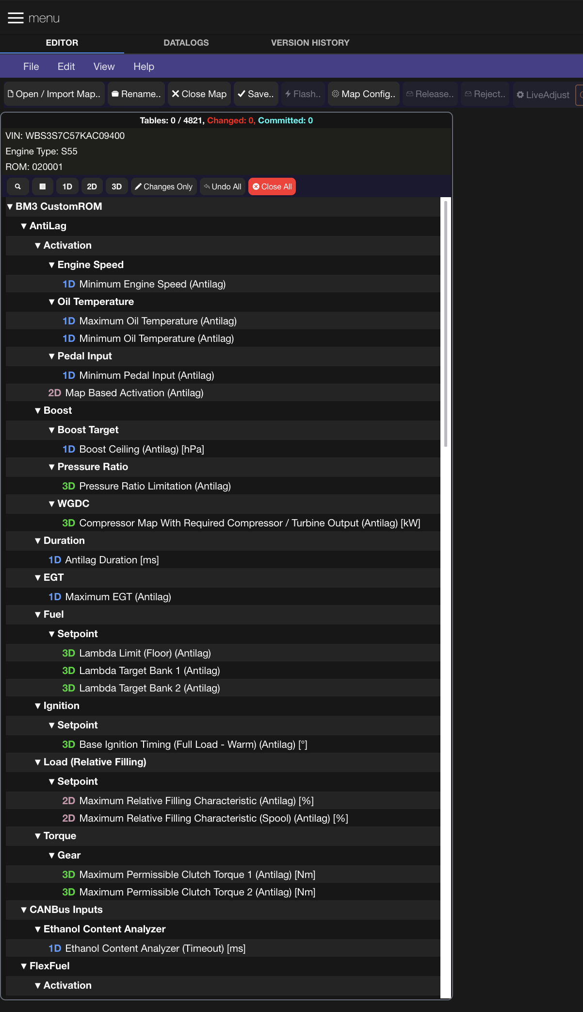
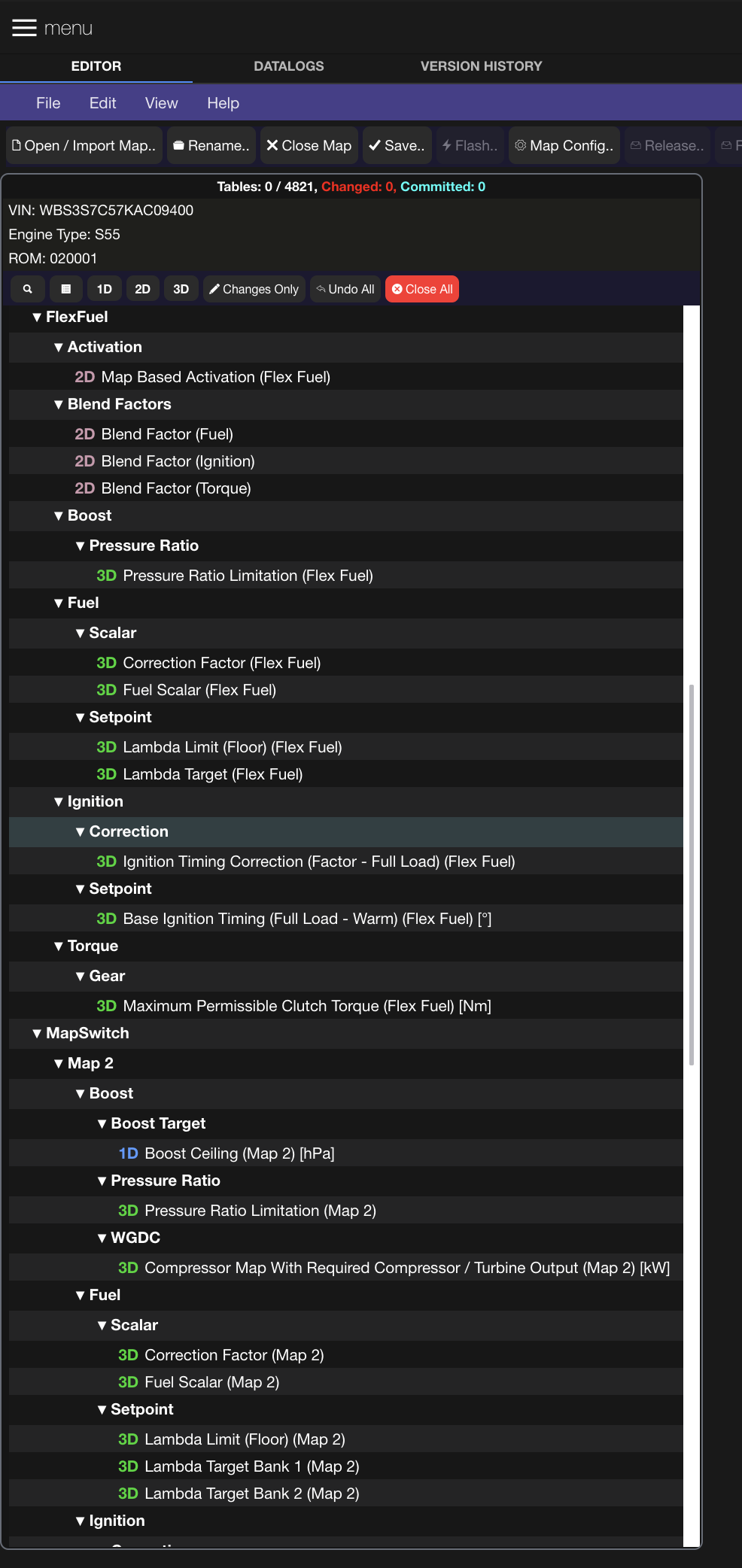
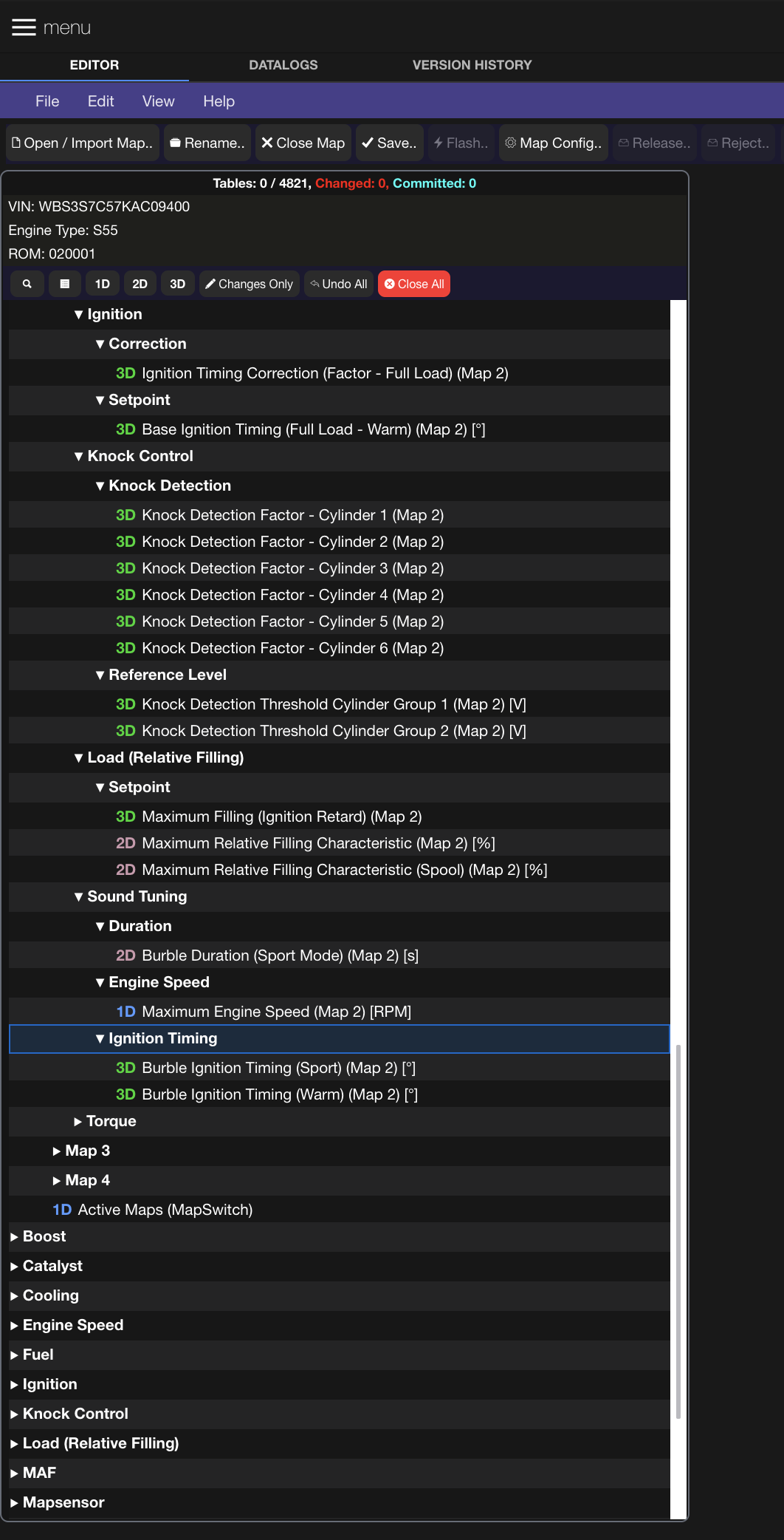
Before opening any tables, let’s first review what tables we have currently available for Map Switching, Flex Fuel and AntiLag that mirror the factory logic of Map Slot 1 for other map slots and from there we know what we have that we can work with (**NOTE: Tables shown are v1.0 of the CustomROM):
We can see there are currently 40-50 tables that are mappable per Map Slot. We’ve chosen this set of tables to be what we’ve felt to be the foundation of key tables that allow for changes in tuning when it came to different power levels on the same or different octane. For example, Map Slot 1 could be the 91 octane map, Map Slot 2 could be calibrated for MS109 Race gas, and so on.
When setting up a multi-map, the base map (Map Slot 1) tables are typically set up for everything unique to the vehicle’s hardware that doesn’t relate to managing power levels. Details around HPFP calibration for instance, larger DI injectors configuration (e.g. S63tu M5 injectors), can be done as part of the non-switchable tables as they wouldn’t change from one map slot to another.
However, desired torque limits, lambda targets, compressor map, fuel injector scalar and correction factors, even burble timing tables, are all adjustable in this release with more to come.
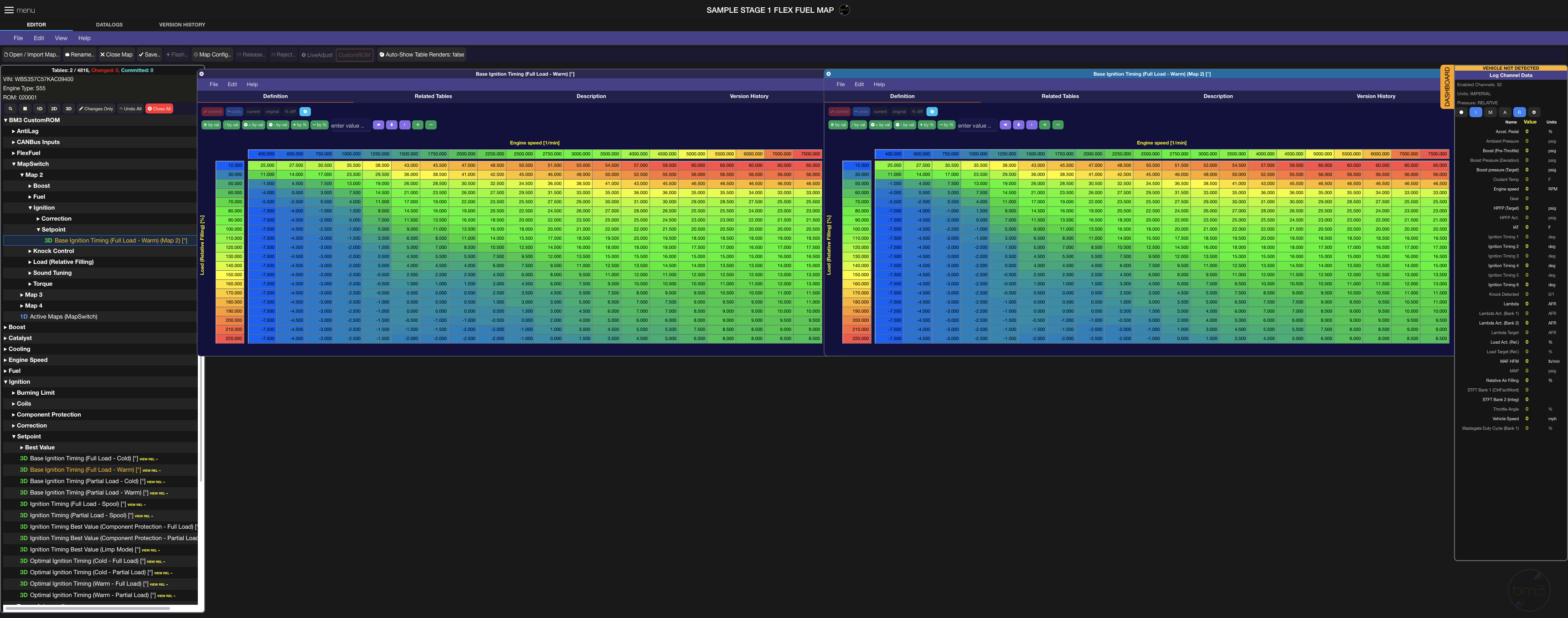
Let’s walk through some of the map-switchable tables as an example. Base Ignition Timing (Full Load - Warm) is the target ignition timing table when the vehicle is operating outside of Cold Start cycle and under full load. We’re showing the Map Slot 1 table on the left and the base map’s Map Slot 2 table on the right. They’re both at stock calibration values to start out.
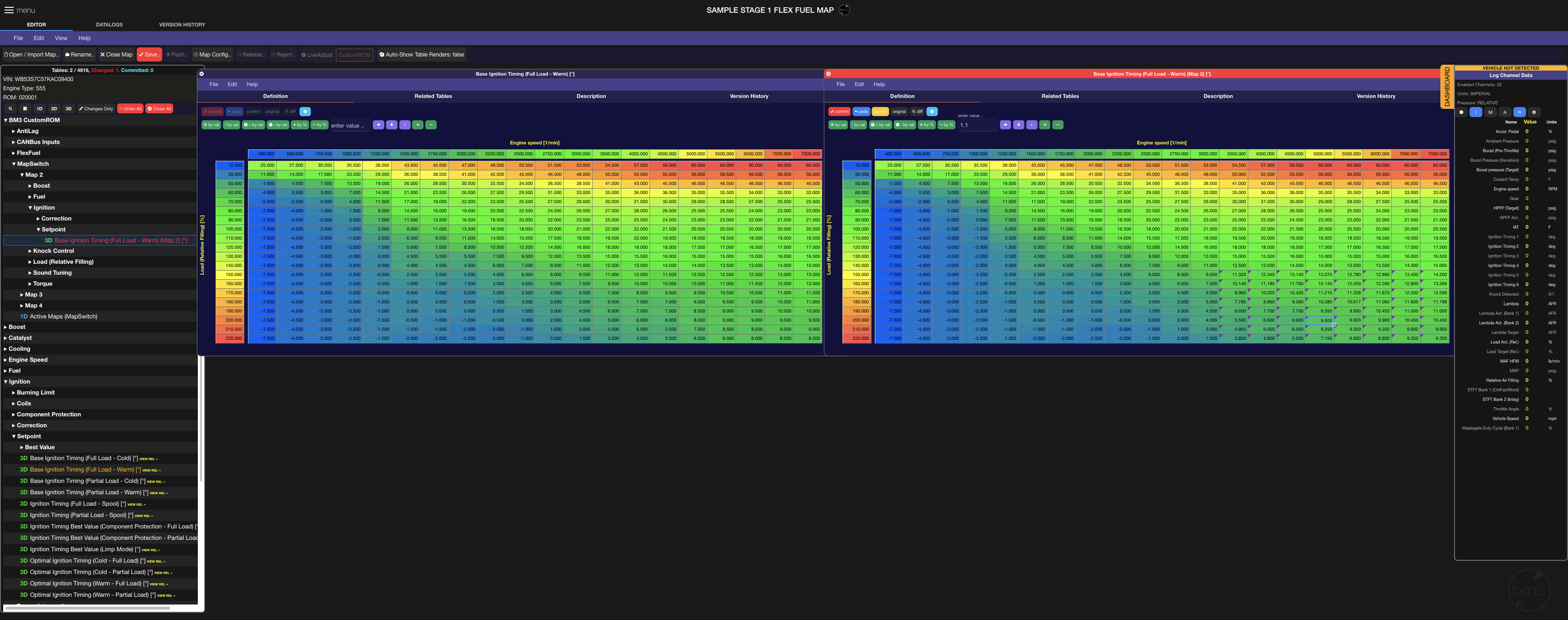
We’ll leave Map Slot 1 at stock timing targets, change Base Ignition Timing (Full Load - Warm) (Map 2) in Map Slot 2 and set up a more aggressive ignition timing profile for higher octane. As an example, we’ve selected the higher RPM/Load area here (bottom right) and increased it by 10% and then used vertical interpolation function to smooth cells in the table above. The changed cells in the table show with a purple indicator in the top left corner of each modified cell.
Clicking on the ‘commit’ button above indicates to the editor that changes to the table are final and hitting Save will pre-select this table for saving to the actual calibration file managed in the cloud.
At this point we’ve got Map Slots 1 and 2 set up for the same torque/load/airflow(boost) targets with just the ignition timing map changed for Map Slot 2, while Map Slots 3 and 4 remain at their base stock values still. Provided octane supports the ignition timing changes we’ve made in Map 2, we will see more power in the area with increased ignition timing.
The rest of the Map Slot tables available can be calibrated in a similar way for the desired changes among map slots which is outside the scope of this document. Fuel correction and scalar tables are available in each map slot to set the base values values for a given map slot and injector duration characteristics. Map Slots 1-4 share every other non-switchable table with the rest of the OEM calibration.
Flex Fuel - Example Map Setup
For vehicles that only see a particular type of octane at any given time this works and has worked for many really well over the years. Users can have custom maps done with multiple map slots without having an Ethanol content analyzer (ECA) device installed on the car if not interested in running alcohol based fuels.
Those that switch from petrol fuel (i.e. pump gas) to alcohol (Ethanol or Methanol) and run different blends with petrol can now do so by letting the DME handle changes in alcohol content which affect cold start-up as well as tuning at high load.
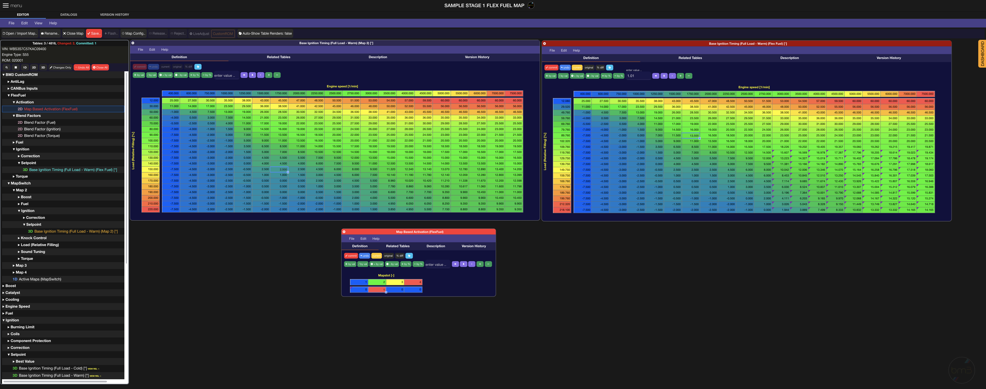
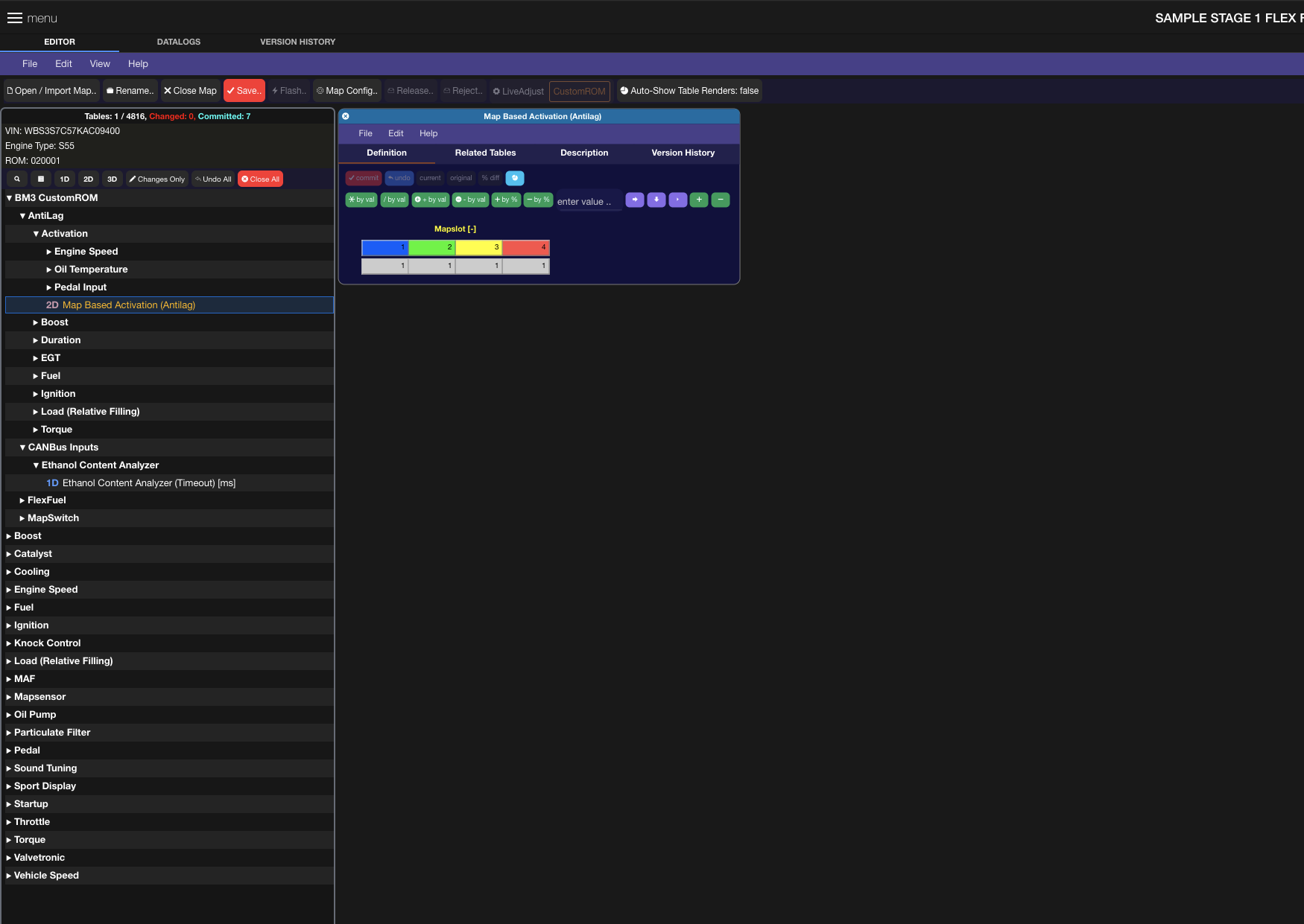
Building on the Map Switching example tables above, we can start by enabling Flex Fuel logic by changing the Map Based Activation (FlexFuel) table for a given map slot, or enabling it in all active map slots (recommended). In this case, we’ll just enable Flex Fuel on Map Slot 2.
On the left side we have the previously set Base Ignition Timing (Full Load - Warm) (Map 2) from Map Slot 2. Let’s assume this is our 93 octane 0% alcohol calibration for Map Slot 2 disregarding torque/load/boost and fuel for the moment. On the right side we have the same table which we can set up for 100% ethanol, our most aggressive ignition timing curve. (NOTE: Tuners experienced with tuning on flex fuel will notice the Flex Fuel timing table isn’t as aggressive as it can be, but details on tuning specifics are outside the scope of this document).
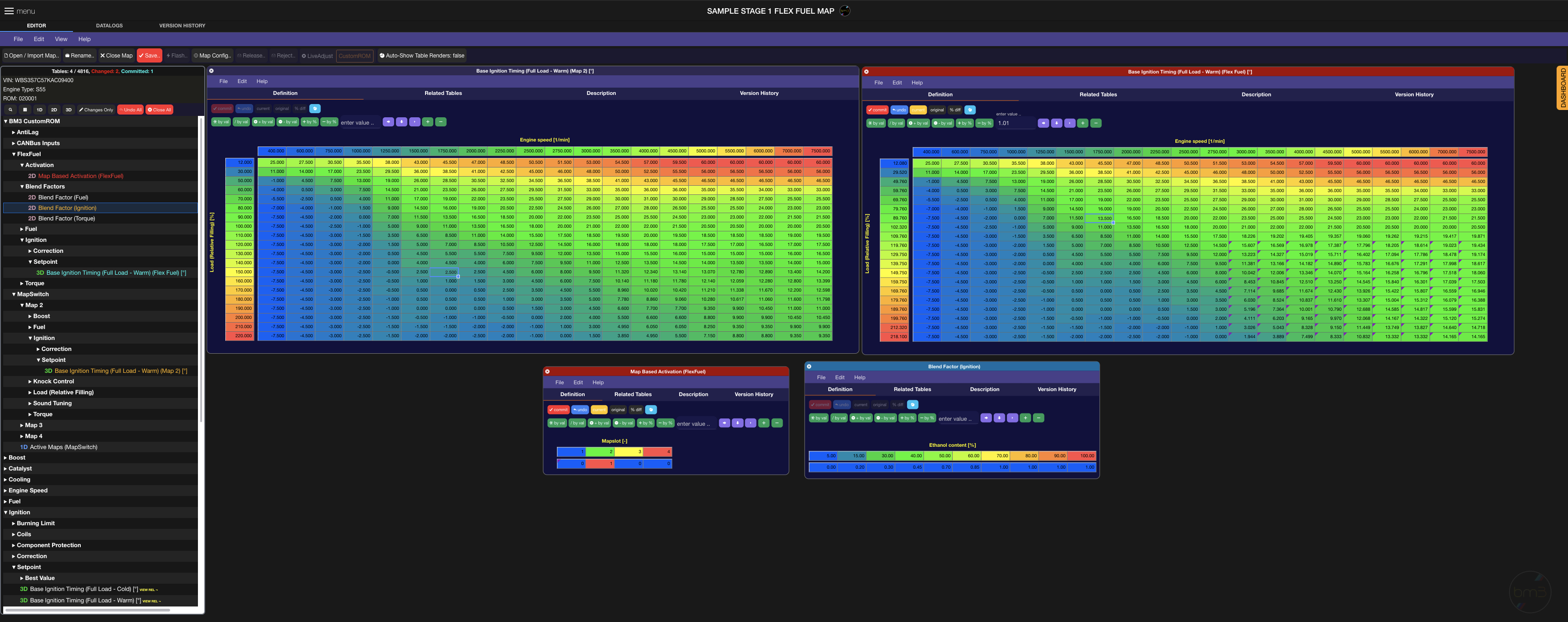
At this point without any other changes, the two tables look pretty much like Map Slot tables and to answer the question on how the DME knows what timing target to run when ethanol sensor reports alcohol concentration between 0 and 100% we show that below via the Blend Factor (Ignition) table:
In this 2D table the axis is alcohol % as reported by a flex fuel sensor over PT-CAN (one of two CANBus in these cars) at CAN_ID 0x0EC as per the Zeitronix CANBus message format. The values are a blending factor for Ignition which interpolates values between the base map slot table (left) and the flex fuel table (right). We can describe this with the following example
For sake of example, we’ll use values at the bottom right-most cell, 7500rpm and 220 load.
Map 2 Ignition Timing Target: 10 deg
Flex Fuel Ignition Timing Target: 16 deg
Lets say our Ethanol Content Analyzer is reporting 50% alcohol. If we look at the Blend Factor (Ignition) table for 50% alcohol, we see a blend factor value of 0.70.
DME uses these 3 values in its calculation of the final Base Ignition Timing Target by using the following equation:
Final Base Ign. Timing Target (After Blend Factor) = Map2 Ign. Target + (Flex Fuel Ign Target - Map2 Ign. Target) x Blend Factor for Ignition
Putting this into actual values for our example at 7500rpm and 220 Load:
Final Ignition Timing Target for 50% ethanol on Map Slot 2 with Flex Fuel Enabled = 10 + (16 – 10) x 0.7 = 14.2 deg
You can see how the underlined portion easily allows for dynamic blending based on ethanol blend factor table setup between the base map table and the flex fuel table in this case.
The same approach is available for Lambda Target on Bank 1 and 2.
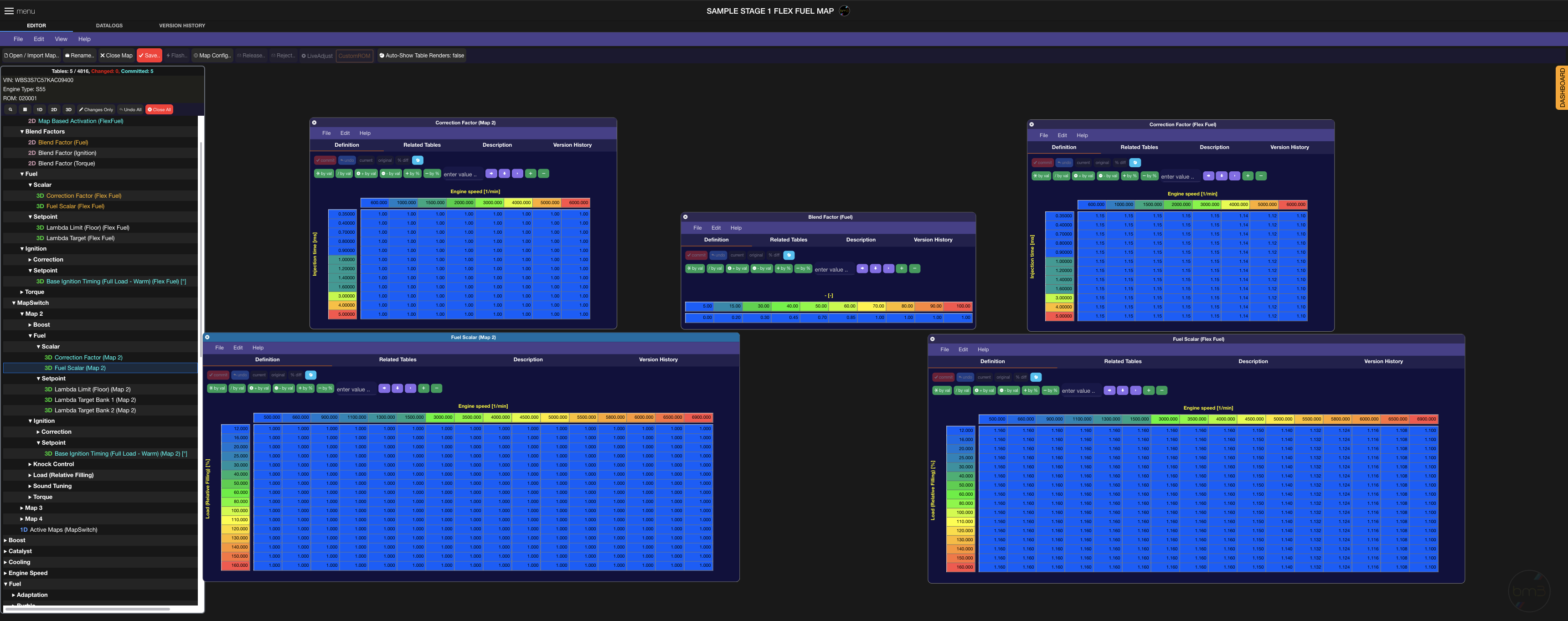
Now we go to one of the most crucial aspects in tuning for alcohol based fuels, fuel injector flow scaling. The tables exposed under Map Switching as well as Flex Fuel, see below:
On the left we have Map Slot 2 base values which we’re using for say a 93 octane pump gas configuration, 0% ethanol. On the right, we have the equivalent tables for Flex Fuel. In the middle we have the Blend Factor (Fuel) table which, similar to the Ignition one shown above, applies the blend factor logic when dynamically adjusting between each of these tables based on alcohol content reported by the Flex Fuel sensor. We’ve exposed RAM channels for datalogging these values to have an easy way to monitor your final calculated/applied scalar and correction values.
In the screenshot, you can also see Lambda Target tables for Bank 1 and 2 which are also blended between Map Slot tables and Flex Fuel tables using the Blend Factor (Fuel) setup.
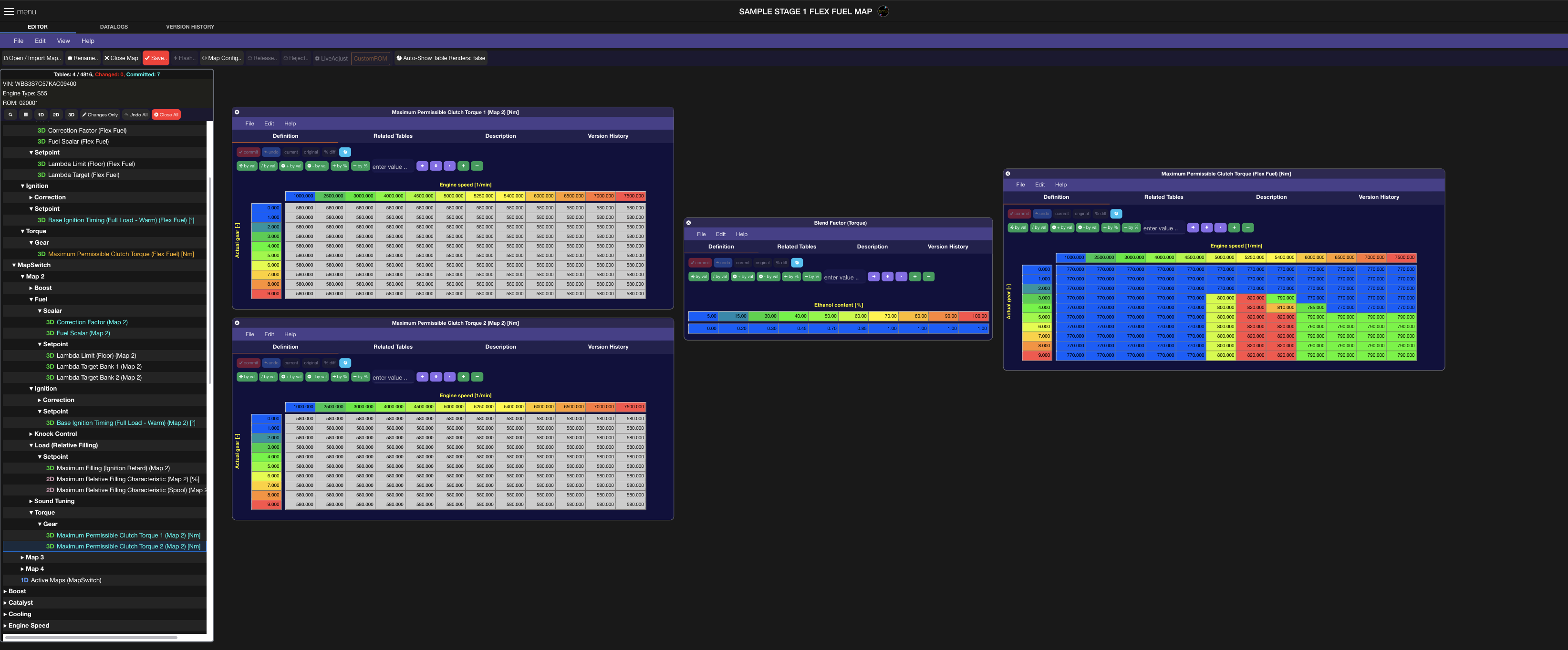
As for changing Torque target, a Blend Factor (Torque) table is used to set up the blending based on ethanol content, see below as an example:
On the left we’ve got the Map Slot 2 Maximum Permissible Clutch Torque 1 & 2 tables set to 580Nm intended for 0% ethanol in the case of this example, while on the right we have a he Flex Fuel Table for Maximum Permissible Clutch Torque and its set to higher values to raise our boost target when on ethanol. With the Blend Factor (Torque) table set up in this way and the same equation to blending as explained earlier, we can see how its not only easy to scale for Torque values as well as visualize exactly where those targets will be.
Overall you can see that in our design around Map Switching, Flex Fuel and Anti-Lag (below) we’ve focused on extending the factory logic without removing any existing failsafes, without reducing resolution on tables used and by putting in tables that show final targets instead of using offset values that are harder to visualize when tuning.
Integrated In-Dash Ethanol Content Check:
To check ethanol content without the bootmod3 app or laptop connected to the vehicle, press and hold the Cruise Control UP/DOWN button in the 1st DOWN position. The Engine RPM (Tach) in the dash will show current ethanol content. Example: 1000rpm, 10% ethanol, 5500rpm 55% ethanol.
Ethanol Content Sensor Override on LiveAdjust Screen:
In the case of a Flex Fuel sensor or ECA device failure, we’ve added a way for the users to override the ethanol content % value seen by the DME. This overrides any existing sensor value and is to be used with ** CAUTION ** and only in the cases where for instance vehicle will not start up on a full tank of ethanol and the sensor has become faulty.
Some have reported wanting to use the override when at race events where the ethanol % of the fuel in the tank is WELL known and having a chance of a sensor failure ending up in poor results is not an option.
** Override disables with ignition in the OFF position.
USE WITH CARE AND UNDERSTANDING IF OVERRIDING SENSOR CONTENT
FLEX FUEL HARDWARE SETUP REQUIREMENTS **
To allow for Flex Fuel tuning, an Ethanol (alcohol) fuel sensor and an Ethanol Content Analyzer (ECA) CANBus device need to be connected to the vehicle’s PT-CAN.
Overview of the how the sensor data travels looks as follows:
Continental Flex Fuel Sensor → CANBus Enabled ECA Board → CANBus (PT-CAN) → DME running bootmod3 CustomROM
Flex Fuel sensor can be installed on the feed line as the factory BMW S55/N55/B58 fuel system is return-less. If using the feed line, it is strongly recommended to use a splitter in the line where the sensor is installed to avoid introducing any fuel flow restrictions at higher power levels with higher fuel volume demand.
Anti-Lag - Example Map Setup
When in the vehicle, AntiLag is activated by the holding the Cruise Control UP/DOWN button in the 1st UP position and following that by pressing on the Accelerator Pedal all the way down (WOT). Pedal threshold is adjustable along with a number of other safeties for temperature and max time in antilag before disabling it for a given activation period.
AntiLag is something that, if improperly set or used extensively, adds great stresses to both engine internals and downstream exhaust components (turbo, catalytic converters) and should be used with great care.
Much like Map Switching and Flex Fuel, AntiLag is a feature that can be enabled on any/all map slots:
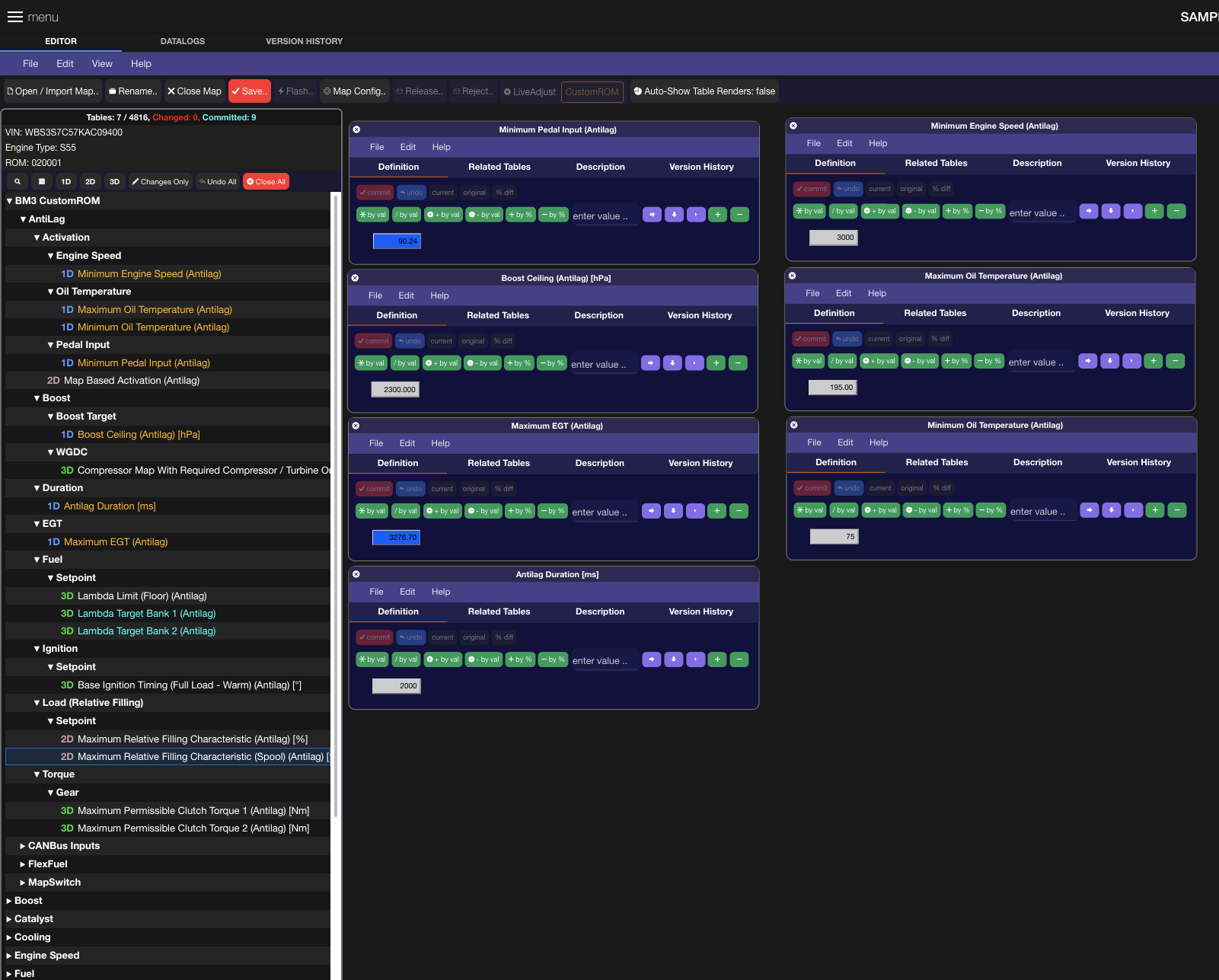
In this case, we’ve enabled AntiLag on all 4 Map Slots. Firstly, the following trigger thresholds, temp and timer safeties are available in this release.
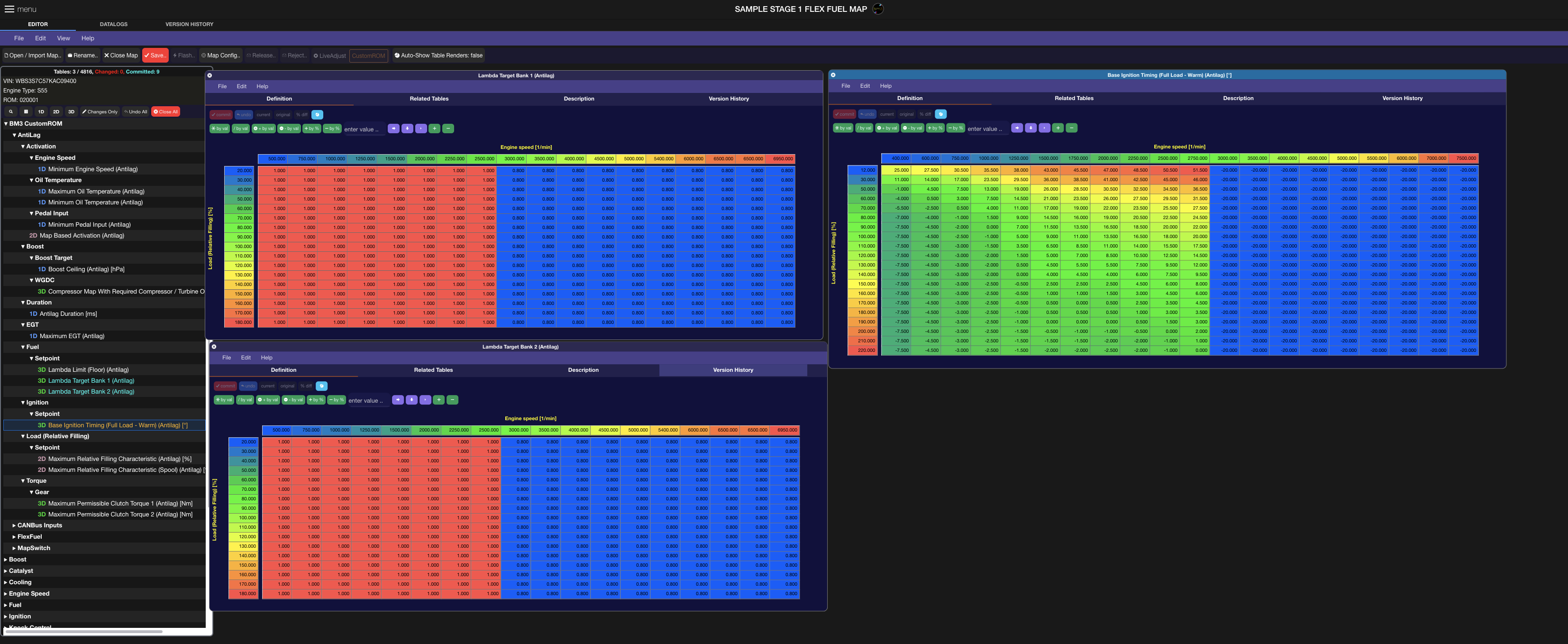
Two key components to building boost using AntiLag are Ignition Timing mostly, and Fuel. We’ve enabled that by adding the following Base Ignition Timing Table for AntiLag and for Bank1/2 Lambda Target tables. You can see as an example, we’re retarding Ignition timing to -20deg past 3k rpm as an example as we’d like to have our Antilag kick in at that point and create load by generating heat in the exhaust manifold allowing the turbine to spin up and create boost. Richer lambda targets help that along but is not required and will depend on a given turbo size / engine / fuel setup.
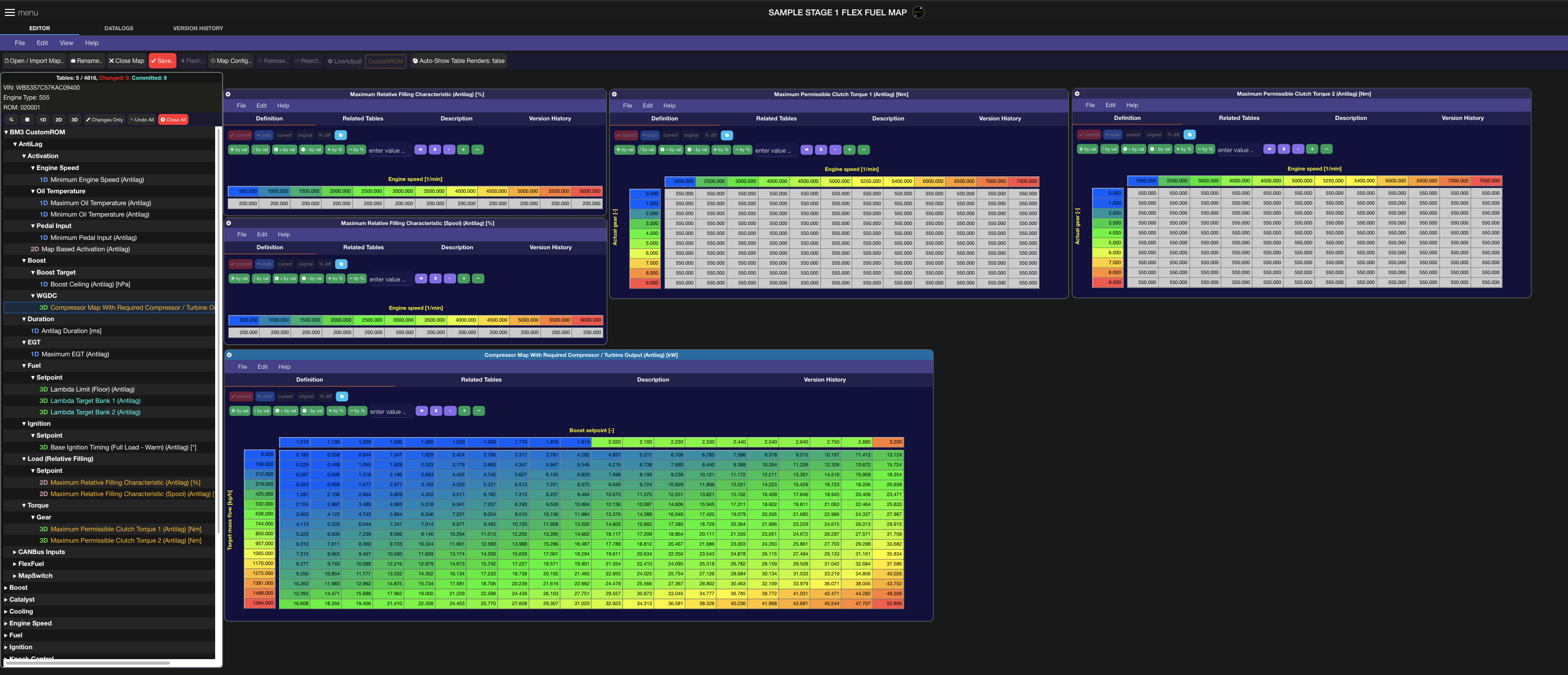
On its own this would have no way of controlling how high boost could reach and the control has been added for both the Compressor map as well as load and torque limiters. Depending on the turbo configuration, and if still using the electronic wastegate, the compressor map can be calibrated for appropriate boost control in AntiLag mode given its Ignition Timing and Fuel targets.
bootmod3 RAM Datalogging Channels (Existing internal values and custom)
When tuning the above features it is highly advisable to add the following CustomROM BM3 RAM channels to your datalogging setup as well as use the appropriate other RAM channels below to get a complete understanding of the task at hand. Default channels that come preset are in some cases limited in what they show and internal RAM variables are a better reference.
